Perfect Fit Every Time: The Maker’s Guide to Precision Engineering Holes
I've seen it a hundred times: a maker spends weeks perfecting a 3D model, obsessing over the fillets and the textures, only to ruin the final assembly because they didn't think about the holes. In industrial hardware, what you remove is just as critical as what you print or mill. If you treat holes as an afterthought, you're just asking for a pile of scrap metal and a lot of frustration.
When I was working on the 3018 cnc-upgrade, I learned the hard way that a poorly designed hole isn't just a void, it's a point of failure. Holes are how we connect our ideas to the physical world. Today, I'm cutting through the theory to give you the practical, ground-level stuff you actually need to know to make your parts fit perfectly the first time.
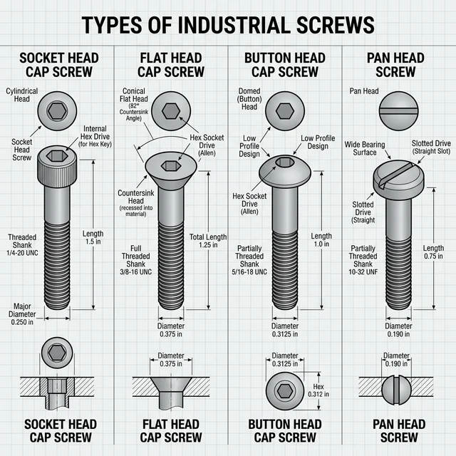
1. Screw Types: Know Your Fasteners
Before designing the perfect hole, you need to understand what you're putting into it. The fastener defines the hole.
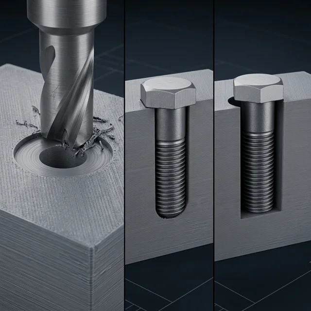
2. Depth: Stop Guessing
The first mistake? Not knowing when to stop. In my workshop, I'm always weighing up Through vs. Blind holes.
- Through (THRU): They go all the way. Great for bolts, but they can look messy on a finished exterior if the bolt sticks out.
- Blind Holes: These stop mid-way. Use these when you want to keep the outside of your enclosure clean. Pro Tip: if you're tapping a blind hole, you need extra depth at the bottom for the 'chips' (the metal scraps). If your screw needs 10mm of thread engagement, drill the blind hole to at least 13mm deep. Your tap will thank you later.
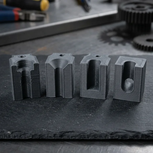
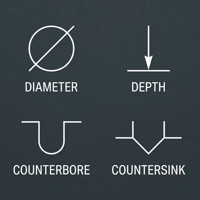
3. The Professional Look: C'BORE and C'SINK
If you want your project to look like a polished product and not a science experiment, your fasteners need to sit flush. This is where most people get lazy.
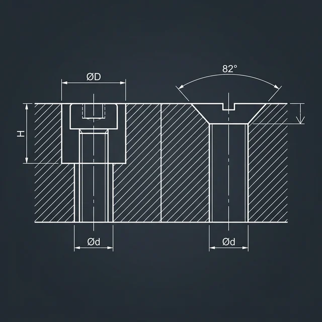
- Counterbore (C'BORE): My personal favorite. It’s a flat-bottomed enlargement for Socket Head Cap Screws. It lets the whole head disappear into the part. It looks professional and provides a great bearing surface.
- Countersink (C'SINK): That conical shape you see for flat-head screws. It's great for low-profile surfaces. Technical detail: Metric flat-head screws use a 90° countersink angle, while Imperial screws (like 1/4-20) normally use an 82° angle. Matching the angle is required for the screw head to sit perfectly flush. Also be careful, because if you sink it too deep in a thin 3D print, you might pull the screw right through the wall.
4. Tolerances & Fits: The +0.2mm Rule
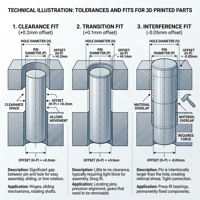
When you design a hole in CAD, the diameter you specify is rarely the exact diameter your machine produces. This is especially true in 3D printing where filament extrudes and shrinks, commonly causing internal holes to print undersized.
- Clearance Fit: The hole is larger than the inserted part, allowing for movement. For most FDM 3D printers, applying a +0.2mm offset to your hole diameter guarantees a reliable clearance fit for bolts and pins.
- Transition Fit: A precise match where parts might need a light tap to connect but hold together firmly. Aim for a +0.05mm to +0.1mm offset relying on printer calibration.
- Interference (Press) Fit: The hole is slightly smaller than the part, causing friction to hold them together permanently. Without heat inserts, 3D printed parts risk cracking if interference fits are too tight, so test a 0.0mm or -0.05mm offset first.
5. 3D Print Special: Heat-Set Inserts
If you're 3D printing high-stress parts, stop screwing directly into the plastic. You need Heat-Set Inserts. These brass threads provide far more strength and allow you to take the parts apart multiple times without stripping the threads.
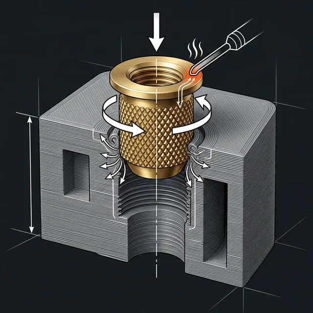
The Best Hole for Inserts: For optimal pull-out strength, use symmetrical, straight (cylindrical) inserts rather than the traditional tapered ones meant for injection molding. When designing the hole, a straight cylindrical cavity is best. As you melt the brass into the plastic with your soldering iron, the straight walls allow for even material flow around the knurls, resulting in maximum pull-out resistance.
6. Material-Specific Strategies
Different materials fight back differently when you try to drill them. Here are quick tips for common workshop materials:
- PLA & ABS Plastics: Drill slow. High RPMs melt the plastic instead of cutting it, causing the bit to bind and the hole to warp.
- Acrylic: Standard drill bits have an aggressive bite angle that cracks acrylic. Use a step bit (unibit) or blunt your drill bit slightly before plunging to scrape rather than cut.
- Aluminum: It's soft and gummy. Without cutting fluid (like WD-40 or proper tapping oil), the aluminum will melt into the flutes of your bit, snapping it mid-cut.
7. The Hidden Detail: Spotface and Clearance
Two hole types often ignored by beginners are the Spotface and the Clearance hole. Understanding these is what separates 'good' from 'great' engineering.
- Spotface (S'FACE): Think of this as a shallow counterbore. If your 3D print has a rough top surface or you're working with a casting, a spotface provides a perfectly flat 'Island' for your washer or bolt head to sit on. No more wobbly fasteners.
- Clearance Hole: You don't want your bolt to fight the hole walls. A Close Fit clearance hole is barely larger than the bolt (for high precision), while a Loose Fit gives you 'wiggle room' to align multiple parts.
8. Precision: Reaming and Tapping
A drill bit is a blunt instrument. If you need a bearing to sit perfectly or a dowel pin to stay put, you need to Ream it. A reamer finishes a hole to a tolerance of microns. When I built the motor mounts for the CNC machine, reaming was the only way to kill the vibration.
If you're threading into metal, you're Tapping. Get a good tap set and plenty of cutting oil. Breaking a tap inside a nearly finished part is a rite of passage I'd rather you avoid. You can also tap directly into stiff plastics (like PLA or ABS) by drilling the standard tap drill size and using a standard metal tap, just go slow to avoid friction melting.
9. Speak the Language
When you send files to a CNC shop or use my Source It service, you need proper notation. Symbols for Diameter (Ø), Depth (↧), and Countersink (⌵) aren't just for show, they're instructions. Clear callouts mean fewer mistakes on the factory floor and a better final product.
The Bottom Line
The difference between a 'prototype' and a 'product' is often just the quality of the connections. Zoom in on your CAD before you hit 'print'. Check your clearances, plan for your fasteners, and don't treat your holes as an afterthought. Precision isn't an accident; it's a choice.
Stuck on a design? Whether you're fighting with a clearance issue or just need a second pair of eyes on your CAD, reach out. I'm here to help you get the details right.
Frequently Asked Questions
What is the difference between a Clearance Fit and an Interference Fit?
A clearance fit leaves a tiny gap (+0.2mm) so a bolt can pass through freely. An interference fit is deliberately undersized, relying on brute friction to hold a pin or bearing permanently in place.
Why use Heat-Set Inserts instead of tapping threads into 3D prints?
Plastic threads strip easily under tension or after repeated use. Pressing a brass heat-set insert with a soldering iron provides industrial-grade metal threads that can handle high torque and endless assembly cycles.
When should I use a Counterbore vs. a Countersink?
Use a flat-bottomed Counterbore (C'BORE) for socket head cap screws. Use an angled Countersink (C'SINK) for flat-head screws to ensure the fastener sits completely flush with the exterior surface of your part.
How do I account for 3D printer shrinkage when designing holes?
3D prints shrink slightly as they cool. To compensate, design holes slightly larger than their target size (typically 0.1mm to 0.2mm tolerance in diameter) or perform a calibration print to measure your specific machine's shrinkage factor.
What is the advantage of using a shoulder screw?
Shoulder screws have an unthreaded, precision-ground shaft (the shoulder) that acts as a bearing or pivot for moving parts, allowing rotation or sliding while securing the assembly with the threaded end.